This project is a 75-cell Formula Student battery management system spanning custom hardware, embedded firmware, diagnostics, desktop tooling, and bring-up planning.
The system is built around an STM32 master board and LTC6812-based measurement boards. It handles cell-voltage acquisition, temperature measurement, passive balancing, pack-voltage and current sensing, isolated isoSPI communication, power-latch behaviour, CAN/USB interfaces, fault handling, and safety permission outputs.
The hardware began from an ENNOID-style reference architecture, but the final system required substantial redesign and remapping. The firmware was rewritten around the actual hardware contract rather than carried over from the original codebase.
System overview
The BMS monitors a 75-cell lithium-ion accumulator using LTC6812 analogue front-end ICs connected over isolated isoSPI links to an STM32 master controller.
The architecture uses separate measurement paths for cell voltages and temperature sensing. The master board selects between the measurement chains, reads pack-level signals, controls safety-related outputs, and communicates with external tools through USB/UART and CAN.
At a high level, the system includes:
- STM32 master board
- LTC6812-based cell-monitoring boards
- separate temperature measurement chain
- LTC6820-based isoSPI interfaces
- pack-voltage and current measurement
- charger-detect and power-latch circuitry
- active-low permission outputs into the shutdown circuit
- embedded C firmware
- binary UART protocol
- desktop monitoring and configuration tool
- simulator/fake target for pre-hardware validation
The main design focus was keeping the electrical design, firmware semantics, and bring-up workflow consistent. Signals such as pack voltage, load-side voltage, shutdown permission, balancing control, and temperature-chain enables have specific hardware meanings, so the firmware was structured around those meanings directly.
Master board hardware
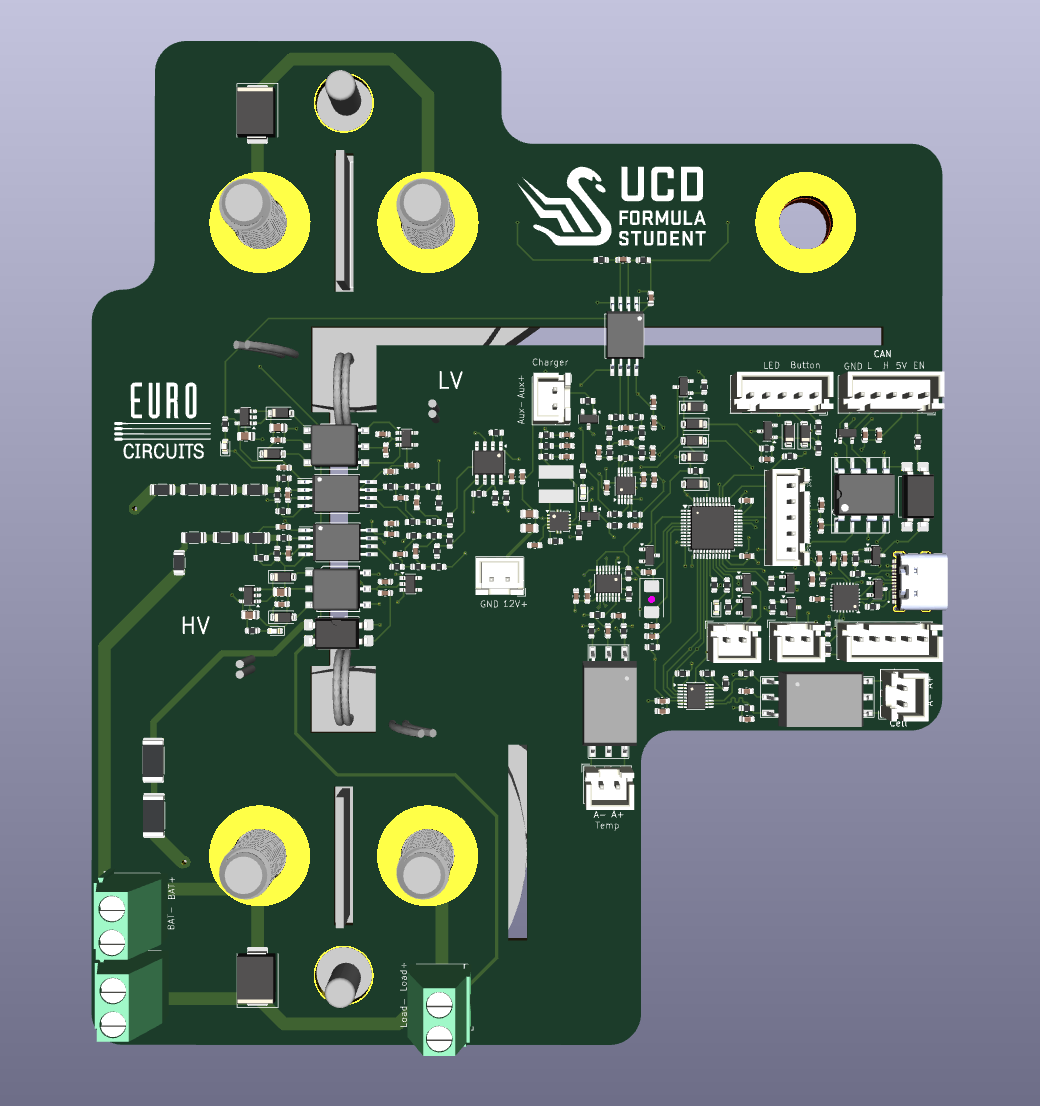 STM32 master board for isoSPI communication, pack measurement, power latch, CAN/USB, and permission outputs.
The master board is the central control and interface board for the BMS. It contains the STM32 controller, isoSPI bridge circuitry, local measurement interfaces, power-latch logic, USB/CAN communication, and outputs into the vehicle safety system.
The STM32 controls two isoSPI interfaces over a shared SPI bus with independent chip selects. This allows the firmware to address the cell-measurement and temperature-measurement chains separately while keeping the physical interface compact.
The board also measures pack-level signals used for system state and precharge validation. Battery-side voltage, load-side voltage, current, and charger presence are treated as separate hardware signals rather than collapsed into a single generic pack measurement. This distinction is important during contactor and precharge transitions, where different nodes in the accumulator can sit at different potentials.
The master board also includes wake and hold circuitry. External wake sources can bring the board up, after which firmware can assert a power-hold signal to keep the system alive. During shutdown, firmware releases the latch after placing safety-relevant outputs into their safe state.
isoSPI communication
Communication between the master controller and the floating measurement boards uses isoSPI. LTC6820 bridge circuits convert the STM32 SPI interface into transformer-coupled isoSPI links suitable for communication across the accumulator measurement chain.
The cell and temperature chains use separate chip selects, so the firmware has to enforce correct chain selection and prevent ambiguous transactions. Communication failures are treated as system-level events rather than ignored driver errors.
Every LTC6812 read is checked using packet error code validation. If a read fails validation, the data is rejected. This is important because corrupted measurements can look plausible, especially in a large cell stack.
The isoSPI design was treated as both an electrical and firmware problem: biasing, termination, wake behaviour, chip-select handling, and PEC validation all affect whether the system can trust the resulting measurement data.
Cell-monitoring boards
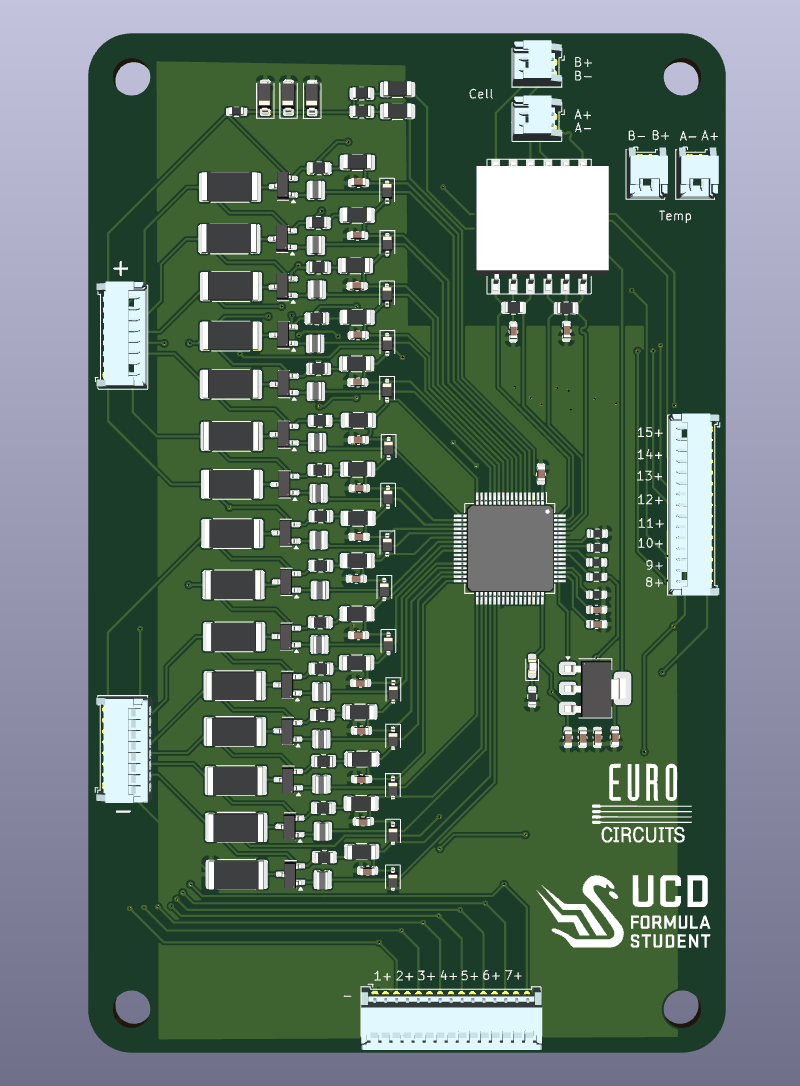 LTC6812-based measurement board for cell sensing, filtering, protection, passive balancing, and isoSPI daisy-chain communication.
The cell-monitoring boards use LTC6812 analogue front-end ICs to measure cell voltages across the accumulator. Each device monitors a group of series cells and communicates back to the master through the isoSPI chain.
The hardware around the LTC6812 includes cell-tap routing, input filtering, protection components, passive balancing paths, and the required local support circuitry for the floating measurement domain.
The cell taps are safety-relevant connections, so the board design had to account for protection, routing density, creepage and clearance, connector access, manufacturability, and accumulator packaging constraints. Full schematics and layout details are intentionally omitted here, but the design work included the practical tradeoffs around fitting a high-channel-count measurement system into a Formula Student accumulator.
Passive balancing is implemented through resistive discharge paths controlled by the LTC6812. The firmware decides when balancing is allowed, while the hardware defines the electrical and thermal limits of the balancing path.
Temperature measurement
Temperature sensing is implemented using a separate LTC6812-based measurement chain. This keeps temperature acquisition independent from the main cell-voltage chain and allows the firmware to handle sensor excitation, settling, conversion, and shutdown explicitly.
The temperature chain uses the LTC6812 measurement inputs to read sensor voltages. The associated switch outputs are used for sensor-bias control rather than cell balancing. The firmware therefore treats the temperature chain as a separate hardware role with its own allowed operations.
This separation is one of the places where the hardware redesign drove the firmware rewrite. Reusing the old firmware model would have made it too easy to apply the wrong meaning to the same class of pins.
Pack measurement and precharge signals
The master board measures battery-side voltage, load-side voltage, current, and charger presence through dedicated signal paths. These signals are used for state estimation, protection decisions, charger behaviour, and precharge validation.
Precharge depends on comparing the battery-side and load-side voltages under the correct conditions. The firmware therefore tracks these as distinct measurements with their own validity and freshness requirements.
The analogue signal chains include isolation, scaling, filtering, and conversion stages. The firmware calibration path has to account for the complete measurement chain rather than only the high-voltage divider ratio.
Permission outputs and shutdown interface
The BMS drives permission outputs into the vehicle safety and shutdown circuitry. These outputs are handled as safety permissions rather than direct actuator commands.
The hardware interface uses defined reset/default behaviour so that the system starts in a safe output state. Firmware must explicitly assert permissions only after the relevant measurements, diagnostics, and state-machine conditions are satisfied.
A major part of the hardware/firmware integration was ensuring that output names, polarities, and downstream meanings were correctly represented in code. Some inherited signal names no longer matched their new electrical function, so the firmware abstractions were rewritten to match the board rather than preserve legacy terminology.
Safety-critical GPIO writes are centralised in the firmware. Other modules can request permission states, but the actual output writes pass through one controlled path.
Firmware architecture
The firmware was rewritten in embedded C for the STM32 around the revised hardware design.
It covers:
- board support and peripheral setup
- dual-chain isoSPI communication
- LTC6812 cell-voltage acquisition
- temperature-chain acquisition
- pack-voltage and current measurement
- charger-detect and power-latch handling
- open-wire diagnostics
- passive balancing control
- fault evaluation
- permission gating
- state-machine logic
- UART protocol handling
- desktop-tool integration
The firmware uses the hardware design as the source of truth. The cell chain, temperature chain, pack measurement paths, shutdown permissions, and power-latch behaviour are represented explicitly rather than hidden behind inherited abstractions.
Measurement data carries validity state. Communication errors, stale readings, failed diagnostics, and configuration problems are treated as conditions that affect whether the system can safely enable outputs.
The fault system tracks cell-voltage limits, temperature limits, measurement validity, communication failures, open-wire diagnostics, pack-measurement issues, precharge timeout, and internal fatal states. Faults are tracked in active and latched form so the system can distinguish current conditions from events that occurred earlier in a session.
Balancing and diagnostics
Balancing is passive and controlled by firmware through the LTC6812 cell chain. The balancing logic depends on valid cell measurements and is inhibited when diagnostic state is uncertain.
Open-wire diagnostics are included because missing or unreliable sense connections can make cell readings misleading. The firmware treats diagnostic status as part of the measurement validity model rather than as a separate debug feature.
Temperature-chain switching is handled separately from balancing. Sensor-bias outputs are enabled only when needed for measurement and disabled afterwards. This reduces unnecessary loading and keeps the temperature-chain behaviour distinct from the balancing path.
Desktop tool and simulator
A desktop monitoring tool was developed alongside the firmware. It communicates with the BMS over a binary UART protocol and supports live telemetry, cell and temperature views, fault monitoring, configuration, diagnostics, and bring-up workflows.
A simulator/fake target implements the same protocol as the firmware. It can produce normal telemetry, fault cases, configuration errors, diagnostic states, and changing live data. This allowed the desktop tool and protocol stack to be exercised before the hardware was available.
The simulator is part of the bring-up strategy. It lets the software and UI paths be validated before first power-on, so physical board testing can focus on electrical behaviour, measurement calibration, isoSPI reliability, and integration with the accumulator.
Validation and bring-up planning
The project includes pre-hardware validation for the firmware logic, protocol stack, and desktop tool. Unit and integration tests cover communication framing, measurement parsing, configuration handling, fault logic, balancing decisions, and simulator interoperability.
Bring-up documentation covers first-flash steps, bench checks, UART smoke tests, chain communication checks, measurement validation, fault injection, and safety-output verification.
Hardware validation is still the next major phase. The remaining work includes real isoSPI timing validation, LTC6812 wake and communication behaviour, analogue measurement calibration, balancing thermal checks, precharge behaviour under real conditions, and verification of the shutdown-interface polarity on the physical vehicle system.
Current status
The hardware design and firmware architecture are prepared for bring-up. The firmware builds, the protocol stack is implemented, and the desktop tool works against the simulator/fake target.
The system still requires full validation on manufactured hardware and in the accumulator environment. The main unknowns are electrical and integration-related: board parasitics, isoSPI margins, measurement calibration, contactor/precharge behaviour, thermal behaviour during balancing, and final safety review.
The pre-hardware work was intended to reduce integration risk before first power-on by making the firmware, protocol, UI, diagnostics, and bring-up procedures coherent ahead of the physical board tests.
Technical highlights
- STM32 master board for Formula Student BMS control
- 75-cell LTC6812-based measurement architecture
- dual isoSPI measurement chains with separate chip selects
- LTC6820-based isolated communication links
- cell-monitoring boards with filtering, protection, and passive balancing
- separate LTC6812-based temperature measurement chain
- pack-side voltage, load-side voltage, current, and charger-detect measurement paths
- firmware-controlled power-latch behaviour
- active-low safety permission outputs into the shutdown circuit
- firmware rewrite around the revised hardware contract
- PEC-validated LTC6812 communication
- open-wire diagnostics and stale-measurement invalidation
- centralised safety-critical GPIO control
- binary UART protocol for telemetry, configuration, and diagnostics
- desktop monitoring tool for development and bring-up
- simulator/fake target for pre-hardware validation
- structured first-flash and bench validation procedure
What this establishes
This project demonstrates full-stack electrical system design across PCB hardware, analogue measurement, isolation, embedded firmware, diagnostics, tooling, and bring-up planning.
The hardware defines the real constraints: floating cell domains, isolated communication, high-channel-count sensing, pack measurement, shutdown permissions, power sequencing, and accumulator packaging. The firmware and desktop tooling were built around those constraints so the system could be tested, operated, and brought up methodically.