Time-multiplexing a compute unit in FPGA design is often described as a simple area-throughput tradeoff: it saves resources, but reduces performance. That is broadly true, but it is too coarse to be useful in practice. The relevant question is not whether sharing helps area or hurts throughput, but under what conditions the tradeoff is actually worth accepting.
To make that question concrete, I implemented three MAC-array variants, ran each through synthesis and place-and-route on the Basys 3, and compared the resulting resource and performance behaviour.
For this design family, compute sharing is not a smooth optimisation knob. It behaves more like a fixed performance cost that only becomes worth paying when it relieves the resource that is actually limiting the design.
The setup
The design family contains three variants. The baseline assigns dedicated hardware to each MAC unit, with no sharing. The LUT-saving variant time-multiplexes the compute while keeping DSP usage unchanged, reducing LUT consumption. The DSP-eliminating variant also time-multiplexes the compute, but removes DSP usage entirely.
All three were measured at array sizes of 16, 32, and 64 MAC units, with a fixed accumulation depth of 32. The conclusions in this post apply to those configurations only.
The chip budget
The XC7A35T is a relatively small device, so the practical meaning of the results depends strongly on which resources are actually scarce.
| Resource | Available | Baseline (64 MAC) | LUT-saving (64 MAC) | DSP-eliminating (64 MAC) |
|---|---|---|---|---|
| LUTs | 20,800 | 4,287 (21%) | 2,694 (13%) | 3,620 (17%) |
| DSPs | 90 | 64 (71%) | 64 (71%) | 0 (0%) |
| FFs | 41,600 | 2,060 (5%) | 1,555 (4%) | 2,324 (6%) |
Even at the largest configuration, LUT and flip-flop usage remain modest. DSP usage is much more constrained: both the baseline and LUT-saving variants consume 64 of the 90 available DSP slices, leaving limited headroom for other DSP-based logic. The DSP-eliminating variant removes that pressure entirely.
Both shared variants incur the same performance cost
For this design family, both shared implementations show the same latency and throughput behaviour.
The baseline completes in 33 cycles, while both shared variants require 65 cycles. Throughput is therefore reduced by roughly a factor of two, with no meaningful difference between the two shared implementations at any tested array size.
This is useful because it separates the performance question from the resource question. In these designs, the choice between shared variants does not change the scheduling penalty; it only changes which resource is being conserved. If the longer schedule is unacceptable, then neither shared design is a viable option.
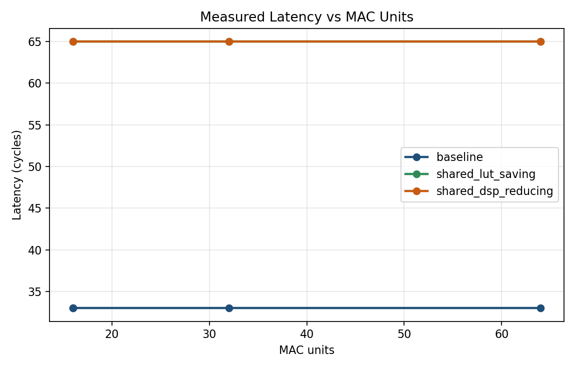 Figure 1. Baseline latency remains at 33 cycles across all measured sizes, while both shared variants remain at 65 cycles.
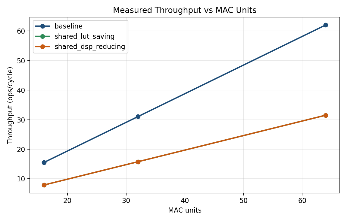 Figure 2. Baseline throughput scales linearly with MAC count. Both shared variants remain at roughly half of baseline throughput across all measured sizes.
The resource savings differ in a way that matters
Although the two shared variants have the same performance penalty, they relieve different resources.
Relative to baseline, the LUT-saving variant reduces LUT usage by about 37% while leaving DSP usage unchanged. The DSP-eliminating variant removes DSP usage completely, but achieves a smaller LUT reduction and uses more flip-flops.
Whether these are comparable tradeoffs depends on the target device. On a device with abundant DSPs and tighter LUT limits, the LUT-saving variant could be attractive. On the XC7A35T, that is not the case. LUT usage is low in absolute terms across all three designs, while DSP usage is already high in the baseline and LUT-saving implementations. On this device, DSP pressure is the more important constraint.
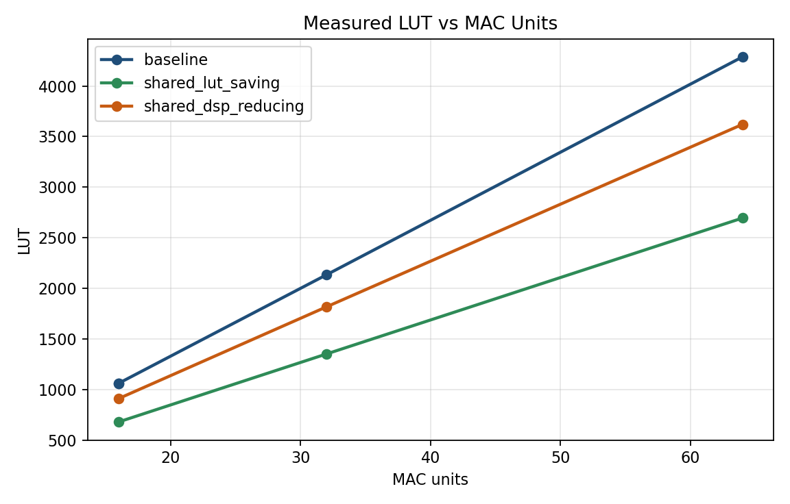 Figure 3. Both shared variants reduce LUT usage relative to baseline, with the LUT-saving variant achieving the larger reduction at each measured size.
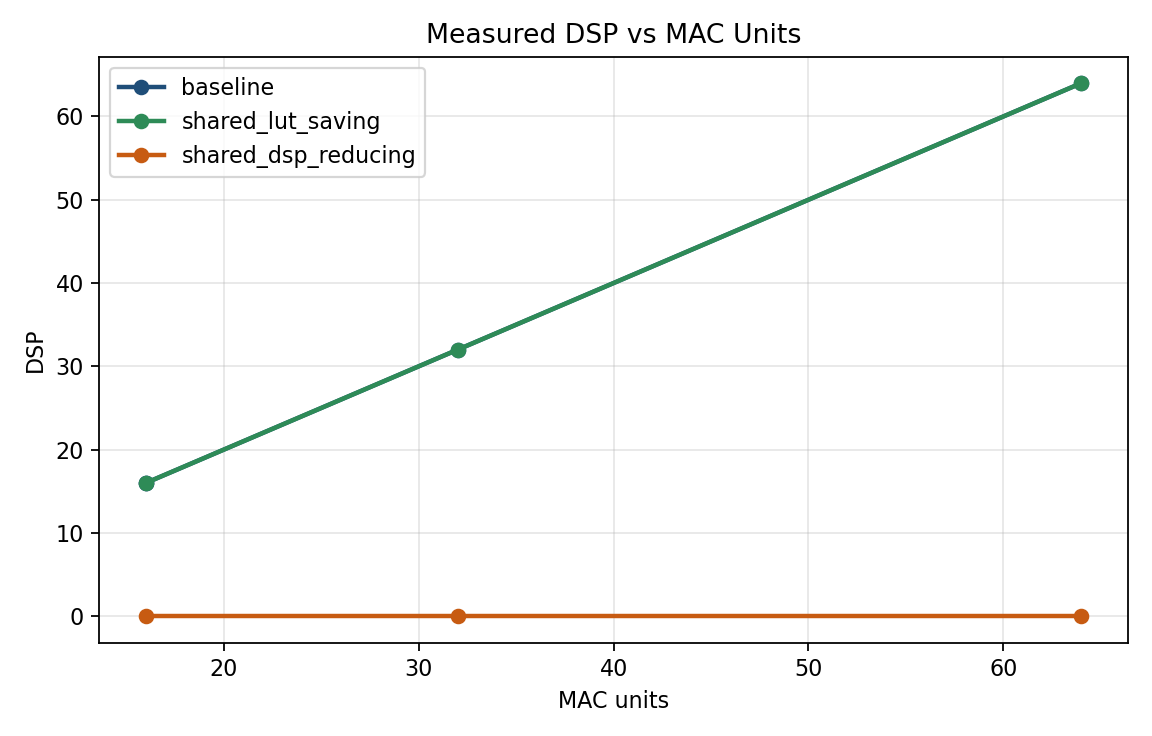 Figure 4. Baseline and LUT-saving DSP usage scale with array size, while the DSP-eliminating variant uses no DSP slices at any measured point.
When does sharing make sense?
Sharing only makes sense when it relieves the resource that is actually limiting the design.
| Situation on XC7A35T | Recommended choice |
|---|---|
| LUT and DSP budgets are both comfortable, and throughput matters | Baseline |
| DSP headroom is needed for other logic, and the longer schedule is acceptable | DSP-eliminating variant |
| LUT budget is genuinely tight, while DSP budget is still comfortable | LUT-saving variant |
On the XC7A35T, this usually reduces to two practical choices: the baseline when throughput matters and DSP usage is acceptable, or the DSP-eliminating variant when DSP slices must be reserved for other parts of the design. The LUT-saving variant is less compelling on this device because it reduces a resource that is not under much pressure.
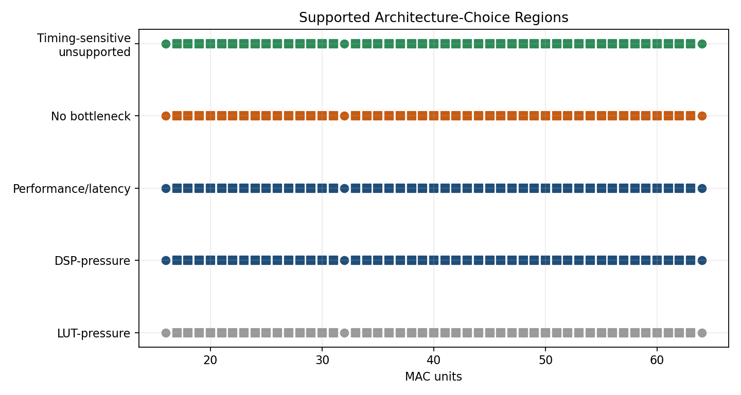 Figure 5. Decision regions over LUT and DSP budget space. On the XC7A35T, DSP pressure appears before LUT pressure across the measured design range.
A note on timing
Worst-case slack varies across implementations and array sizes, and I do not think the current data supports a clean timing-based switching rule. On this part, timing behaviour should be checked with a fresh implementation run rather than inferred from another design point.
The takeaway
In this MAC-array family, sharing introduces a fixed performance penalty. The relevant design question is therefore not whether sharing saves resources in the abstract, but whether that penalty is justified by the specific resource constraint of the target device.
For the XC7A35T, LUTs remain relatively unconstrained while DSPs become scarce much earlier. Under those conditions, the DSP-eliminating variant is the more relevant shared design, not because it is universally preferable, but because it addresses the resource that is more likely to limit the overall system.
Target device: XC7A35T-1CPG236C (Basys 3). Available resources: 20,800 LUTs, 41,600 flip-flops, 90 DSP slices. Measurements taken post-routing at three array sizes with a fixed accumulation depth of 32. Interpolation is only assumed within the measured range.